Tuesday, October 17, 2006

conisbrough castle concept

This is Conisbrough castle in South Yorks. Its a unique shape in this country but the idea is borrowed from a French design. Anyway I spent far too much time, more than was healthy trying to get this in to model. It was a concept for the Ivanhoe trust who own the castle.


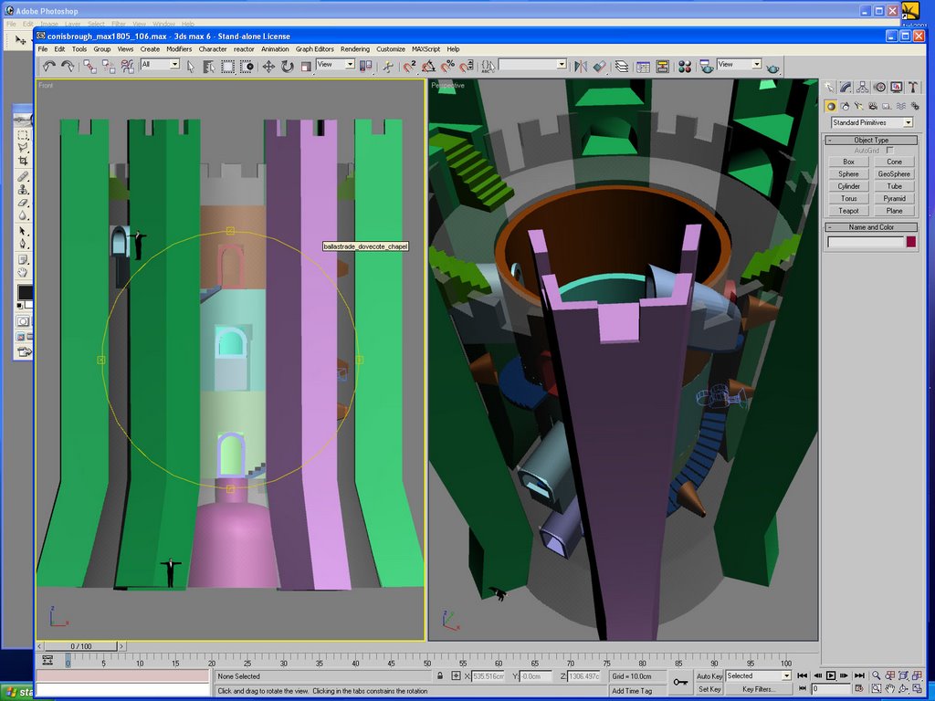
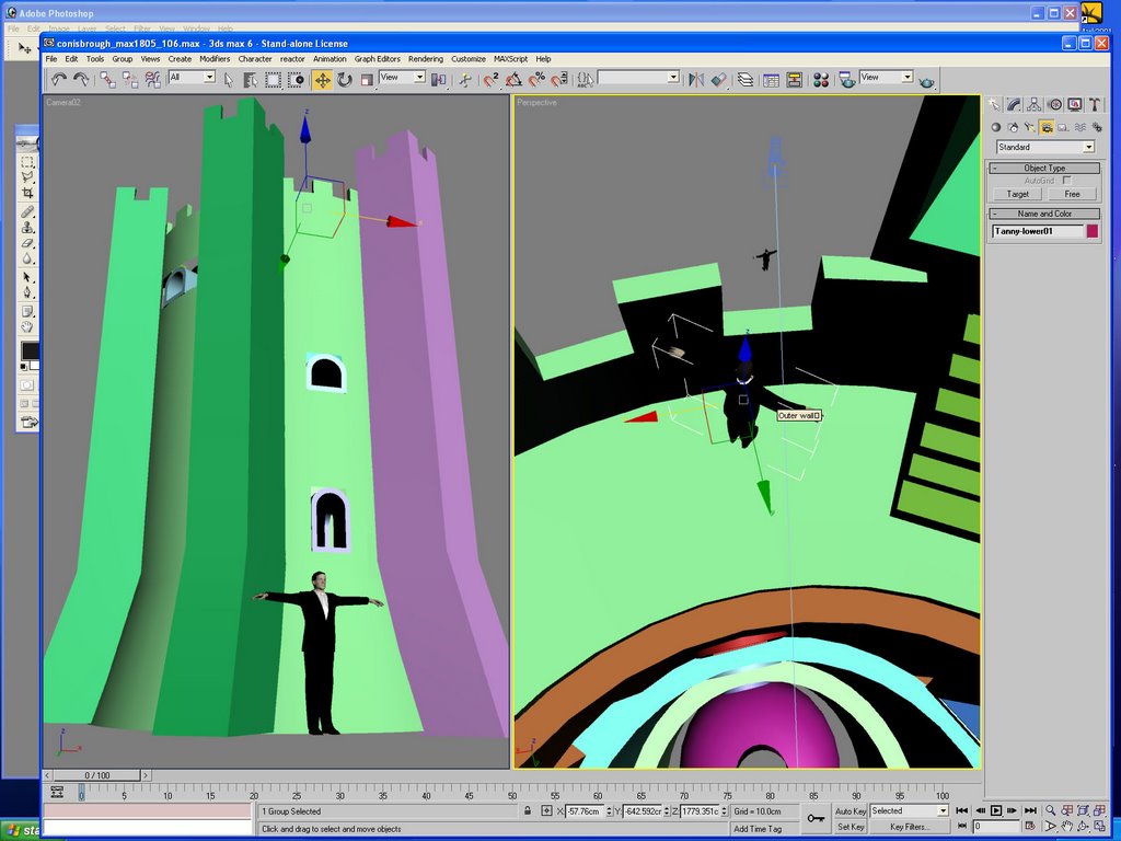
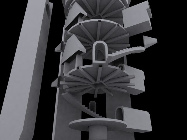
First up is a birds eye straight from Max then a few views with xray on to see the spiral staircases and recesses etc.


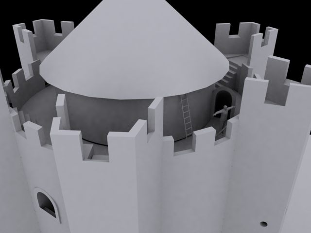
A few light-tracer renders and then some attempts at texturing the castle.


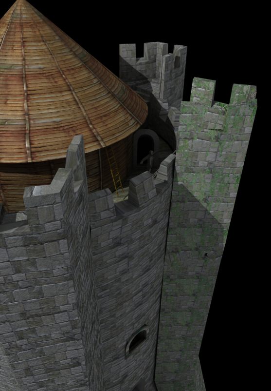
Concept for 3D viz of Conisbrough castle

The images and animations on the CD show off the potential for this visualisation proposal.
Making use of 3D graphics with virtual cameras and the ability to display photo-realistic renderings gives the viewer who may be unable to visit the real site for one reason or another at least a sense of the scale and environment of the structure. With the ability to visualise camera flyby’s from ground to flagpole and trips up the spiral stairs and perhaps a bucket eye view from well floor to keep roof there are views that even real visitors would never see. Throw into this mix control over lighting and even seasonal changes – imagine watching the progression of shadows as the castle is seen bathed in early morning June sunlight through to sunset in late evening all in 60 seconds!
I wanted to show at least the possibilities with some renderings of other structures (a few churches and real world street scenes) as well as some of the Conisbrough keep. I have included an un-textured keep showing how its possible to display cut-out or x-ray views of the internal structure; some shots of a typical texturing method which shows at this stage very clean looking textures! And typical flybys of how it’s possible to have complete control over lights and cameras.
I hope this goes some way to showing the potential. With that said it would be useful if you could contribute what you’d expect from such a system and how you would envisage it working i.e. Using touch panel screens with multimedia presentations or purely still images used as historical teaching support. I have some ideas that I have imagined from the beginning:-

1. User interactivity. The ability to initiate animations; listen to audio clips; control lighting etc
2. A slideshow of pre-rendered photo-realistic images showing castle and keep.
3. An artist’s impression of how the construction progressed.
4. Overlays of the castle in 11th and 21st centuries, showing how much or how little it has deteriorated.

When I initially thought of this concept I looked at Thornton Abbey and imagined how it might be re-constructed back to its former glory given what is still remaining now. I don’t know whether that is too ambitious given the intricate craftsmanship involved or indeed whether there is enough information in the archives to make a worthy guess That is why I think Conisbrough castle’s condition makes this idea a more realistic goal I believe.

M.Hodsman 2004


Monday, October 16, 2006

Vehicles: miscellaneous

First off here are a couple of stills from an engine animation for a college. Created in Cinema4D. Following these are 2 stills from a WIP of a VW camper done in Maya.

A little raydiosity rendering...


Vehicles: Hires bikes....

The Excalibur started out in 3DMax and then I had to learn Cinema4D for a job. I ended up rejigging this in Cinema and textures in illustrator/photoshop as ever.


Vehicles: Playstation2 targeted vehicles....


Vehicles: Old escort from early 90's....

Created this in Lightwave in the early 90's. I had a macintosh and I think Lightwave was about as good as it got for non SGI owning people. I wrote an article explaining the spline method for a now defunct 3D magazine. looks a bit dated now.


An early 90's article incorporating the Escort.
Accurate modelling techniques in Lightwave

Lightwave includes a number of organic modelling tools. These tools allow smooth flowing and intricate sweeps, impossible to obtain with other methods. The single biggest drawback with MetaNurbs is ultimately a lack of control. It isn’t long before the number of control points required for an accurate rendition of say an aircraft fuselage become unwieldy and constantly hamper your efforts.

The process usually begins with a cube primitive (figA.)

sliced a number of times in all axes. Hitting ‘Tab’ initiates the metanurb cage. All of the cube’s vertices and edges then become control points for the Nurbs patch. (figB). The process whilst fluid and quick is seemingly at worst a shot in the dark.

Game character designers are often working with the main visual character being around 250-300 polys. The total maximum for fluid real time graphics on a current Playstation may bottom out around that 400-500 if it has to move at high frame speeds. Being creative with textures is an absolute must. Creators of static images or animations for FMV sequences are not constrained by a particular gaming console’s capabilities, but nevertheless huge polygon counts can bring the design system to it’s knees and the vital visual feedback disappears. This is sometimes the case with the 3d digitising method. Whilst it is obviously an accurate method, algorithms are usually needed to reduce the polygon count to a usable figure with less than consistent results.

For the Escort Cosworth model in this article I needed compound sweeping curves, cut out sections and relatively accurate dimensions for it to appear…like an Escort! A low polygon approach would have probably utilised the MetaNurbs tools with its benefits of quick previews and ease of modelling. However the compromise is as mentioned earlier, a lack of accuracy and control.

There is one tool or rather technique that allows complete accuracy over all meshes and curves. It is somewhat less trendy than the MetaNurbs/MetaForm or MetaBalls approach included in Lightwave; that is the spline cage method. It is still hard to visualise the model and involves a somewhat lengthy preparation stage. It is still easier than manipulating a full 3 dimensional mesh all in one go.

Creating the templates

It is necessary to get hold of orthographic views where possible of the object in question in top, face and side views. Some manipulation is necessary in your paint package to scale up and align all views as in (fig1).

Import these three files into Lightwave as backdrop images.

(fig2) shows Lightwave with the templates in place and a typical spline patch being worked on. The actual process of creating a spline cage will be explained using the Escort’s foglight assembly. Zooming in until all three views are centred on the part, begin tracing around the template by placing points only.(fig3).

Note with a symmetrical object such as this, working with only one half of the object greatly reduces the work involved. This is our first dimension and we need to switch our ‘working’ view in order to create the rest of skeleton or frame work which supports the mesh. A note here that the spline tool requires at least 3 and preferably 4 splines in order to create predictable meshes. The more splines used, the more accurate the mesh will flow and of course the more polygons created. (Fig4)

shows our 4 splines selected and the patch tool applied. The real control with the patch tool is that the dialogue box allows the selection of the number of parallel and perpendicular polygons to create. This is useful because in the process of creating a complex object, it may involve many such trace/spline/patch operations. These distinct patches need to be welded together at a later stage and having a uniform number of points on all patches makes life so much easier. (fig 5)

shows the completed foglight assembly. It comprises of 12 patches with the points merged together to form the single mesh. The patches all consist of a low value for the perpendicular/parallel requestor box. The overall shape is still apparent and the overall poly count low enough that it doesn’t become difficult to work with. If it is found that more polygons are needed at a later stage then it is a straightforward task to subdivide as many times as necessary.

The entire Escort model was created in this fashion. It is analogous to real world car manufacture. Visually isolating sections such as wings,bonnet, etc; tracing and creating the splines and using consistent patch sizes we end up with a collection of ‘car panels’. We ‘weld’ up the panels and end up with our workable car shell. (fig 6) shows the completion of one half of the shell before we apply the mirror tool. It’s inevitable that things don’t go quite as smoothly as these words suggest; It took much tweaking and many attempts to get the car into a shape I liked. The process is still infinitely quicker and controllable than Newtek’s much touted MetaNurbs approach though in the author’s opinion.


Some of the textures created in illustrator & photoshop...

Vehicles: New Cosworth

First up is the subdivision Escort Cosworth done in Maya....
I like Maya, didn't at first but as there is only a fag paper between Maya & Max I tend to favour Maya because I inhereited a shedload of tutorial books and videos.